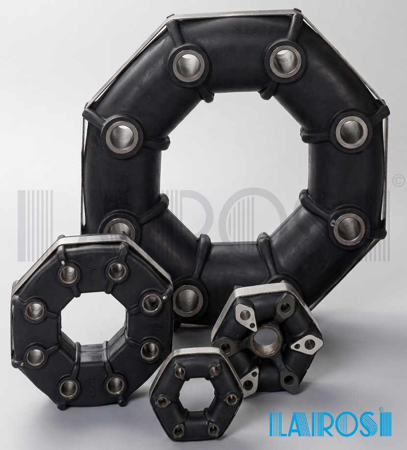
Giubo Couplings are one of the most famous metal-rubber Flexible Couplings. In our Larosi warehouse we have them available at stock, both original Pirelli® under SAGA license and in the new hexagonal and octagonal sizes, ready for the same-day shipping. We proud ourselves in being the main European supplier, with the widest range of dimensions: Hexagonal and octagonal series, metric and imperial dimensions, ready for fast shipping from Larosi.
The Giubo coupling, designed and manufactured by SAGA, thanks to the simplicity and rationality of its concept, has elastic characteristics superior to those of any other type of coupling.
The Giubo is made of rubber blocks arranged in a polygonal shape.
At each vertex of the polygon, in order to allow connection to the shafts by means of yokes, special metal parts with through holes are embedded in the rubber.
The circumference on which the centers of the through holes lie has a smaller diameter in the assembled coupling than in the free coupling. In this way a precompression is obtained in the rubber blocks, which keeps the tensile stresses generated by the torque within safe limits, to the advantage of safety and durability.
Years of use in the most varied fields, with ever-increasing diffusion, testify to the reliability and efficiency of the Giubo coupling.
Catalog
Request our Giubo Couplings catalog
Prices
Request prices in € and quotations for Giubo Couplings
Consulting
Contact us to request advice from Larosi experts
Elastic characteristics of the Giubo
IN TORSION the Giubo coupling can deform up to considerable limits thanks to the favorable shape factor of the blocks.
Thanks to this characteristic the Giubo has excellent damping and also acts as a shock absorber between the driving and driven parts, absorbing very high torque peaks.
CARDANIC DEFORMABILITY is high because the rubber works in shear and torsion.
As a guide, a normal operating angle of 2 ÷ 3° can be indicated, with peaks up to 4 ÷ 6°.
RADIALLY the permitted displacements are modest, although sufficient to absorb slight assembly defects.
AXIALLY the Giubo allows considerable displacements, of the order of a few millimeters, without the need for splined shafts, with consequent simplification and cost reduction of the construction.
Due to the particular shape of the coupling, the transmission of motion between two shafts in which a cardanic angle is present is ensured with almost perfect constant velocity.
Types of Giubo
The Giubo currently in normal production can be classified into three categories:
- Standard series Giubo in millimeters
- Giubo series in inches
- Special Giubo.
The difference between the first two categories is implicit in the definition: one series has dimensions in millimeters, the other in inches.
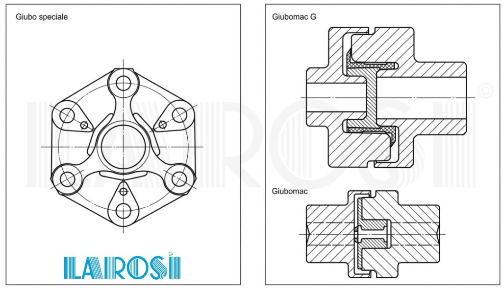
Special Giubo have an incorporated metal yoke that serves for centering and force transmission, or in any case differ from the standard types in some construction detail.
In the previous classification no account is taken of the fact that:
- Giubo can be hexagonal or octagonal in shape
- the rubber blocks can have round, elliptical, square or rectangular cross-section.
Why Choose Larosi Giubo Couplings
Original Pirelli® products. The hexagonal elastic couplings of our production come both from the continuity of the official SAGA / PSA Pirelli® Anti-Vibration Systems / CF Gomma production line and, in the case for example of new sizes and new designs, from the use of the same adapted or renewed molds, with a guarantee of qualitative continuity over time. Larosi was in fact the official distributor of industrial spare parts for PSA Pirelli® Anti-Vibration Systems / CF Gomma until the companies of the Pirelli® group produced these couplings, then continuing the production of the same to guarantee continuity to the market. In our warehouse you can find original Pirelli® Giubo Couplings as well as new recently produced high-quality sizes.
Complete range in stock. Hexagonal and octagonal Giubo, metric and inch series, as well as Giubomac and Giubomac G.
Technical sizing support. The Larosi technical office verifies the correct code before order confirmation.
Custom and special sizes. Production to drawing for non-standard applications, starting from the schemes available in the catalog.
What is a Giubo Coupling
The Giubo is an elastic rubber coupling that connects two rotating shafts — driving and driven — absorbing misalignments and vibrations while transmitting torque.
It is a coupling consisting of rubber blocks arranged in hexagonal or octagonal form. The metal parts with through holes are used for fixing to the shafts. The rubber block can have different cross-sections. The basic cross-section is circular; however, space requirements may advise the use of different sections.
The usefulness of Giubo transmission couplings
The Giubo Coupling, which has high torsional elasticity and excellent damping, transmits very high torques while decisively reducing motion irregularities. Axial displacement can be of the order of a few millimeters. Consequently, the elastic characteristics of the Giubo Coupling are superior to those of any other type of coupling.
The insertion of an elastic coupling between the driving shaft and the driven shaft is particularly advantageous because:
- it guarantees the absorption of irregularities of the driving torque and of any vibrations
- it eliminates critical regimes
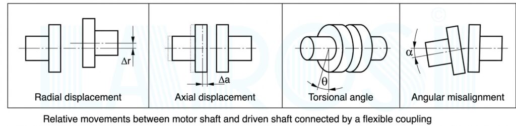
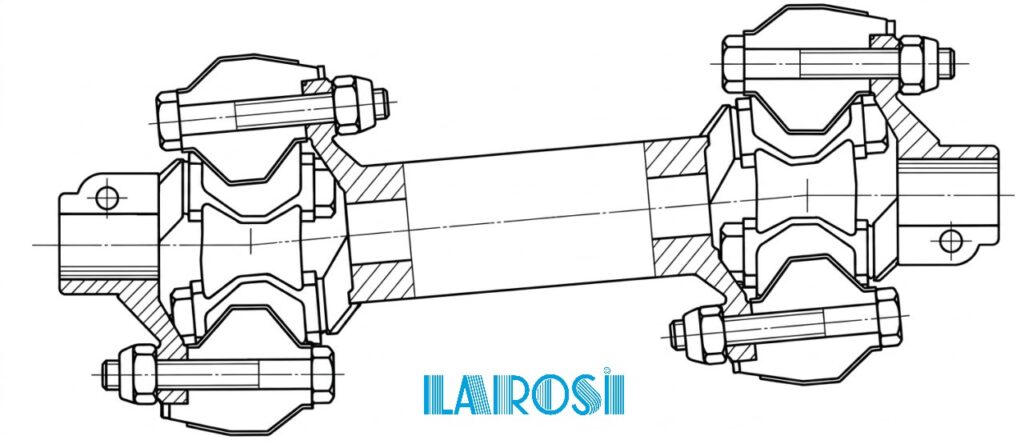
- it allows relative movements between the two shafts of the following types: torsional, cardanic, radial, axial (see figure 2).
The elastic coupling:
- simplifies and makes the construction more economical, because thanks to its deformability it to a certain extent performs the function of a cardan joint and of a splined shaft
- increases the life of mechanical parts by absorbing vibrations, particularly torsional ones, which are the primary cause of failures
- is silent because it has no backlash
- does not require lubrication.
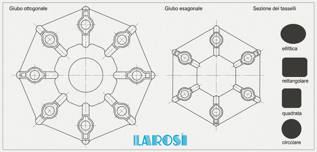
The Giubo is based on a simple construction concept: rubber blocks arranged in a polygon, with metal parts with through holes embedded at each vertex for connection to the shafts via yokes. The diameter on which the centers of the holes lie is smaller in the assembled condition than in the free coupling: this generates the precompression of the blocks, which keeps the tensile stresses induced by the torque within safe limits, to the advantage of safety and durability. For this reason each coupling is supplied already precompressed, locked by a circumferential metal band that must be removed only after assembly is completed.
The choice of the suitable coupling must be made taking into account various factors including:
- power to be transmitted
- shaft offsets and misalignments
- rotational speed
- overall dimensions
- environmental conditions
- motion irregularities.
The basic parameter for selection is nevertheless the normal torque (Mₙ).
For a correct choice, the normal torque characteristic of the coupling, given in the attached tables, must be higher than the normal torque of the transmission, which is calculated as indicated below.
Known:
N = rated power of the motor in HP
n = rated speed in rpm
the rated torque transmitted M is calculated.
$$M = 716 cdot frac{N}{n} quad text{Kgm}$$
or, if N is expressed in kW,
$$M = 973.5 cdot frac{N}{n} quad text{Kgm}$$
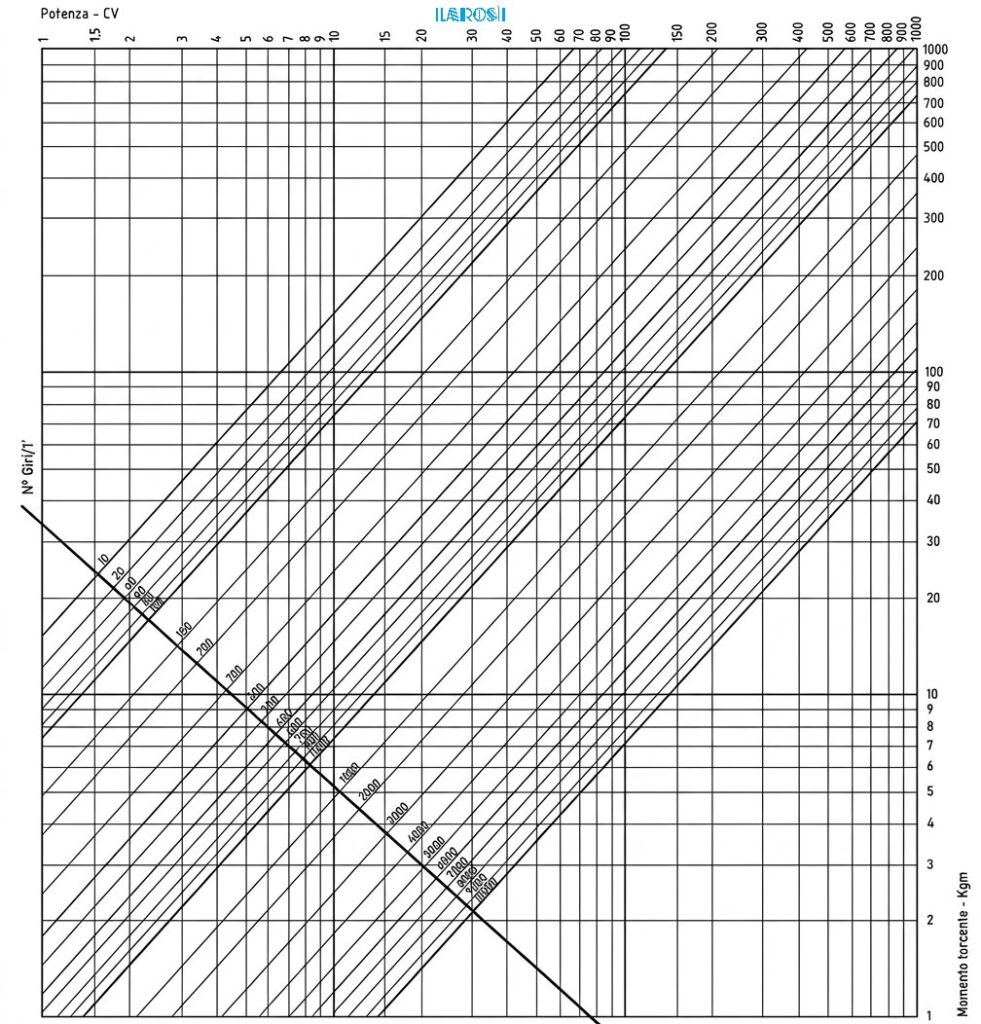
To make the determination of M easier, a nomogram is shown in figure 3.
The intersection of the vertical (power in HP) with the diagonal (n in rpm) determines a point; the horizontal line passing through this point indicates M (in Kgm) on the right-hand scale.
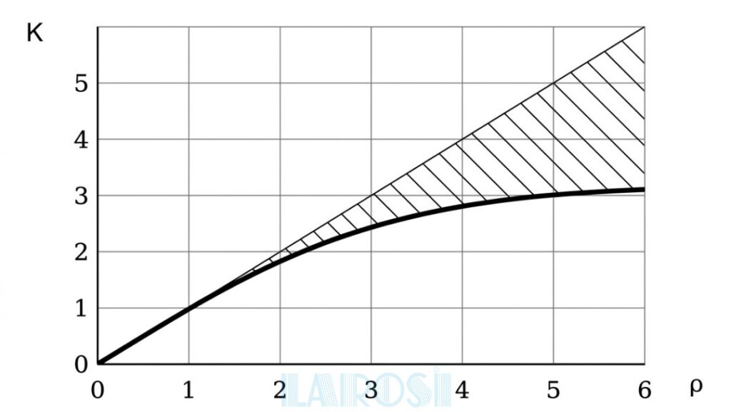
Once the rated torque is known, the normal torque is determined by means of a safety coefficient K that takes into account torque irregularities
$$M_n = KM$$
In the diagram of figure 1, K is shown as a function of θ, the transmission irregularity coefficient.
The hatched area of the diagram represents the possible range of choice of K.
The transmission irregularity coefficient depends on the driving machine and the driven machine.
As a guide, Table 1 shows the values of θ in the most common cases of application.
For cases not covered we recommend contacting the Technical Office.
Having obtained Mₙ, the couplings that have an Mₙ value equal to or higher than the calculated one are sought in the tables.
For the couplings found, the compatibility of the following characteristics is checked:
- maximum speed
- axial, radial and cardanic deformability
- overall dimensions.
After that the choice can be considered final, subject to verification of any environmental aggressiveness.
The correct name: Giubo
The correct technical term is Giubo Couplings, not “Guibo”, “Jubo” or “Juboflex”. The name comes from the fusion of giunto (coupling) and Boschi, the engineer who conceived the construction principle at SAGA. Over time the term has spread as a generic denomination for this type of elastic coupling, regardless of the manufacturer, in sectors ranging from marine to heavy industry.
Main functions
- Absorbs irregularities of the driving torque and transmission vibrations.
- Eliminates critical resonance regimes.
- Allows four types of relative movement between the shafts: torsional, cardanic, radial and axial.
- In many configurations replaces cardan joints or splined shafts, simplifying and reducing the cost of the construction.
- Operates without mechanical backlash, therefore silently.
- Does not require lubrication or periodic maintenance of the elastic part.
Example of Coupling Selection
Coupling
- Application: Diesel engine – Electric generator
- Number of engine cylinders: 3
- Rated power (N): 50 HP
- Rated speed (n): 2600 rpm
- Maximum cardanic angle: 2°
Limits and Dimensions
- Radial displacements: Negligible
- Axial displacements: Negligible
- Maximum outer diameter: 180 mm
- Distance between shafts: 100 mm
Coupling Verification Table
| Model / Series | Rotational speed | Axial deformability | Radial deformability | Cardanic deformability | Overall dimensions |
|---|---|---|---|---|---|
| GIUBO 83249 (standard series) | YES | YES | YES | YES | YES |
| GIUBO 87804 (inch series) | YES | YES | YES | YES | YES |
| GIUBOMAC G 85308 (short series) | YES | YES | YES | NO | YES |
| GIUBOMAC G 85309 (medium series) | YES | YES | YES | NO | YES |
| GIUBOMAC G 85310 (long series) | YES | YES | YES | NO | YES |
The possible choice is the GIUBO 83249 or 87804 couplings
The discrimination between the two types must be made according to the need for dimensions in millimeters or in inches.
Technical Characteristics and Materials
Rubber compounds
Giubo Couplings are manufactured in natural rubber compound, chosen to ensure the best elastic characteristics under standard operating conditions. For special applications — environments in contact with oils, extreme temperatures, exposure to salt water — synthetic compounds with special characteristics are available. The reference torsional stiffness is calculated on rubber with hardness 55 Shore.
Metal components
The metal parts with through holes of the Giubo Couplings are embedded at each vertex of the rubber polygon. These are used for fixing to the shafts via yokes and are generally made of steel. When it is necessary to reduce the centrifugal force on the bolts at high rotational speeds, light alloy parts are used. On some Giubo Coupling models there are anti-rotation teeth: projections that engage in the seats provided on the flanges, preventing the metal parts from rotating during bolt tightening.
Product Families
Giubo. It is a coupling consisting of rubber blocks arranged in hexagonal or octagonal form.
The metal parts with through holes are used for fixing to the shafts.
The rubber block can have different cross-sections.
The basic cross-section is circular; however, space requirements may advise the use of different sections.
The Giubo coupling, which has high torsional elasticity and excellent damping, transmits very high torques while decisively reducing motion irregularities.
Axial displacement can be of the order of a few millimeters.
The elastic characteristics of the Giubo coupling are superior to those of any other type of coupling.
Special Giubo. They differ from the standard series by the presence of an incorporated metal yoke that serves for centering and force transmission or by the particular shape of the metal parts.
From the point of view of elastic performance, special Giubo couplings are comparable to standard Giubo couplings.
Giubomac and Giubomac G. These are couplings consisting of two metal hubs and an intermediate elastic element.
In Giubomac the metal parts are in light alloy. In Giubomac G the metal parts are in cast iron.
Giubomac couplings are characterized by good torsional elasticity, ease of assembly, compactness and safety.
| Type | Construction | Ideal Applications |
|---|---|---|
| Standard hexagonal Giubo | Rubber blocks arranged in hexagonal form, metal parts with through holes at each vertex | Medium-low power transmissions, compact dimensions |
| Standard octagonal Giubo | Rubber blocks arranged in octagonal form, greater number of fixing points | Higher torques for the same outer diameter |
| Special Giubo | Incorporated metal yoke for centering and force transmission, or non-standard geometry of the metal parts; elastic performance comparable to a standard Giubo coupling | Applications with particular construction requirements, to drawing |
| Giubomac | Two light alloy metal hubs with intermediate elastic element | Compact assemblies, good torsional elasticity, ease of installation |
| Giubomac G | Like Giubomac, but with cast iron hubs | Applications requiring greater mass and rigidity of the hubs |
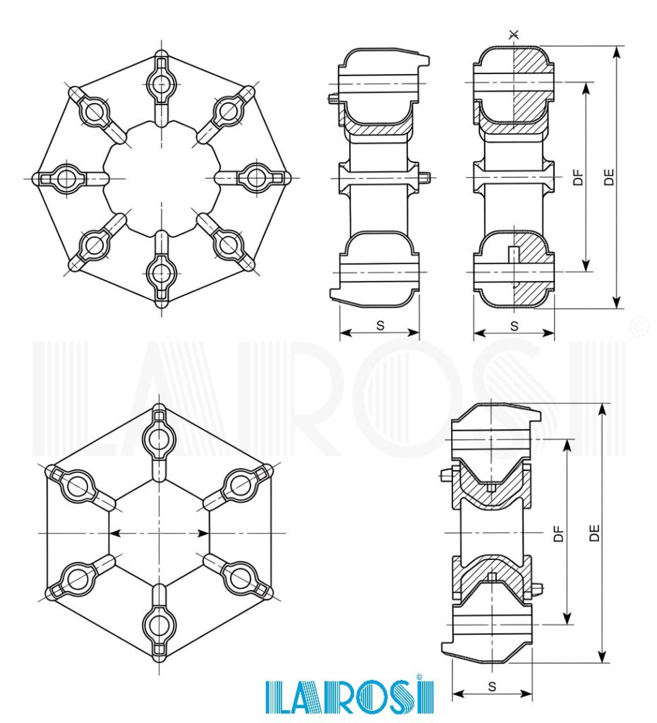
Cross-sections of Giubo Coupling Blocks
The basic cross-section of the rubber block is circular. Where the available space requires it, elliptical, rectangular or square sections are provided, while maintaining comparable elastic performance.
Series Classification
- Standard series — dimensions in millimeters (Table 2 of the catalog).
- Inch series — dimensions in imperial units (Table 3 of the catalog).
- Special series — require drawing confirmed with Pirelli®, custom-made for the specific application (Table 4 of the catalog).
Giubo Couplings Production
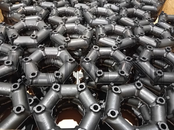
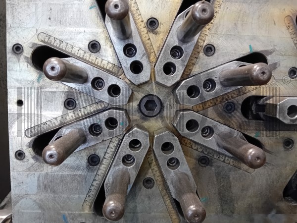
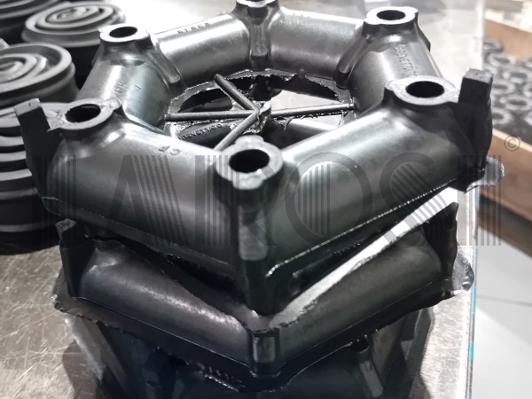
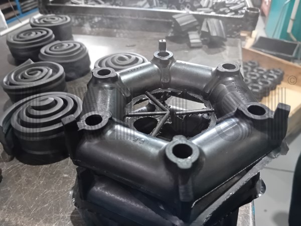
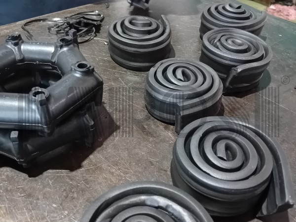
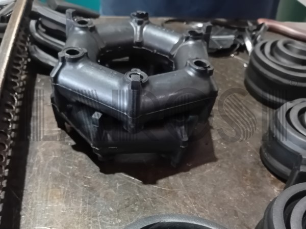
Here are some of the production stages of our Giubo Couplings production line, from compound preparation, to molding of the hexagonal shape, to installation of the supports, to assembly of the retaining band.
How to Find the Correct Giubo Coupling
In most cases no calculation is necessary: it is sufficient to compare the dimensions of your application — diameter, thickness, cardanic angle, overall dimensions — with the dimensional tables of the catalog (standard series, inch series, special series) and identify the corresponding Giubo coupling code.
If the size you need is not in the catalog, we produce Giubo Couplings to measure. You can use the blank drawing available in the catalog to indicate the dimensions and technical data of your request.
Can’t find the code you need, or have doubts about the choice? Send us the dimensions of your application, or the completed drawing: our technical office will confirm the correct Giubo coupling or assist you in custom production.
Applications of Giubo Couplings by Sector
- Marine and Nautical Coupling between engine and gearbox/propeller shaft on inboard engines, damping of shaft line vibrations, 6- and 8-hole configurations. For environments in the presence of salt water.
- Automotive and Commercial Vehicles Elastic couplings for drive shafts on rear-wheel and all-wheel drive platforms, reduction of vibrations to the chassis, spare parts for cars, trucks and buses.
- Railway and Heavy Machinery Applications on locomotives, earth-moving machines and tractors, where the transmission must absorb high torques and significant misalignments.
- General Industrial Machinery Pumps, compressors, generators and electric motor–centrifugal pump couplings, among the most common combinations indicated in the irregularity coefficient table.
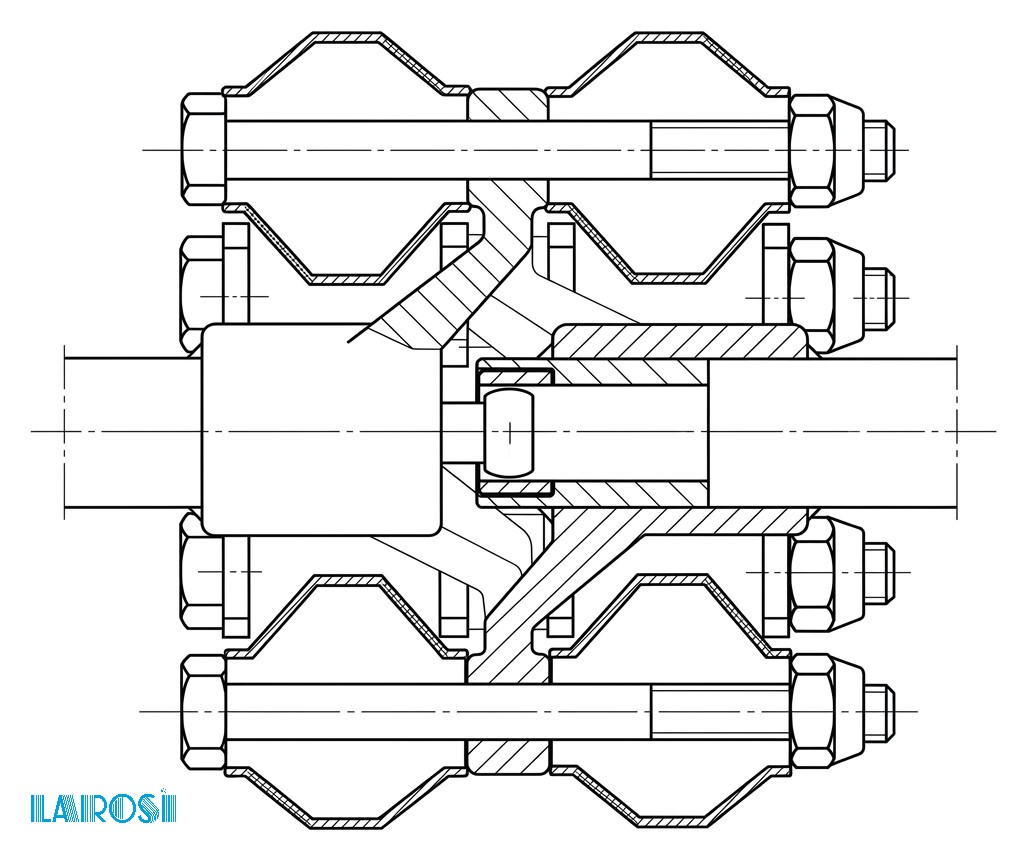
When a shaft is not supported near the Giubo coupling and rests with its weight on it, a mechanical or elastic centering is recommended which can easily find space inside the Giubo coupling itself (see an example in the Diagram). By itself the coupling is sufficiently balanced. However, it is advisable to balance the coupling-flange connection system.
Complete Giubo Couplings Catalog
The complete catalog of Pirelli® Giubo Couplings, with all dimensional tables (standard series, inch series, special series) and the OEM cross-reference table, is available for consultation and download in PDF format.
Standard series Giubo
| Form number |
Type | Torque | Hole circle diameter Dv |
Outer diameter DE |
Cardanic angle α |
Axial displacement Δa |
Torsional stiffness |
Thickness S |
Metal parts material |
Block size |
Bolt diameter |
Block section |
Rotational speed |
Teeth | |
|---|---|---|---|---|---|---|---|---|---|---|---|---|---|---|---|
| Kgm | mm | mm | degrees | ± mm | Kgm/° | mm | mm | mm | rpm | ||||||
| normal | max | norm. | norm. | max | |||||||||||
| 81487 | E | 4 | 10 | 65 | 91 | 3 | 3 | 0.5 | 28 | Fe | Ø 22 | 8 | C | 11000 | — |
| 84283 | E | 6 | 15 | 72 | 100 | 3 | 3 | 0.6 | 29 | Fe | Ø 23 | 10 | C | 10000 | YES |
| 80998 | E | 7 | 17.5 | 76 | 108 | 3 | 4 | 0.9 | 31 | Fe | Ø 26 | 10 | C | 9500 | — |
| 81144 | E | 8.5 | 21 | 85 | 118 | 3 | 4.5 | 1 | 32 | Al | Ø 27 | 10 | C | 8500 | — |
| 83052 | E | 8.5 | 21 | 85 | 118 | 3 | 4.5 | 1 | 40 | Fe | Ø 27 | 10 | C | 8500 | YES |
| 83409 | E | 11 | 27 | 85 | 125 | 3 | 4.5 | 1.4 | 40 | Al | Ø 32 | 10 | C | 8000 | — |
| 85829 | E | 11 | 27 | 85 | 124 | 3 | 4.5 | 1.4 | 46 | Fe | Ø 32 | 10 | C | 8000 | YES |
| 83183 | E | 11 | 27 | 85 | 125 | 3 | 4.5 | 1.4 | 32 | Al | 29 x 32 | 10 | C | 8000 | — |
| 81156 | E | 12 | 30 | 95 | 134 | 3 | 5 | 1.4 | 40 | Fe | Ø 30 | 10 | C | 7500 | — |
| 85079 * | E | 14 | 35 | 96 | 135 | 3 | 5 | 1.5 | 40 | Fe | Ø 32 | 10 | C | 7500 | YES |
| 82931 | E | 16 | 40 | 100 | 142 | 3 | 5 | 2 | 46 | Fe | Ø 35 | 12 | C | 7500 | — |
| 83939 | E | 16 | 40 | 100 | 142 | 3 | 5 | 2 | 46 | Fe | Ø 35 | 12 | C | 7500 | YES |
| 84572 | E | 16 | 40 | 100 | 142 | 3 | 5 | 2 | 46 | Al | Ø 35 | 12 | C | 7500 | — |
| 85511 * | E | 23 | 57 | 113 | 160 | 3 | 5.5 | 3.5 | 50 | Fe | Ø 40 | 14 | Q | 6000 | YES |
| 86645 * | O | 23 | 58 | 96 | 135 | 2 | 3 | 3.5 | 44 | Fe | □ 32 | 10 | Q | 8000 | YES |
| 83249 | O | 25 | 62 | 116 | 157 | 2 | 4 | 5 | 46 | Fe | Ø 35 | 12 | C | 6500 | — |
| 84396 | O | 27 | 67 | 100 | 146 | 3 | 5 | 2.9 | 46 | Fe | 36 x 39 | 12 | R | 7000 | — |
| 84072 | E | 30 | 75 | 132 | 181 | 3 | 7 | 3.3 | 50 | Fe | Ø 40 | 14 | C | 5500 | — |
| 84395 | O | 37 | 92 | 116 | 159 | 2 | 4 | 7 | 46 | Fe | 36 x 38 | 12 | R | 6500 | — |
| 83790 | O | 40 | 100 | 122 | 172 | 2 | 4 | 8.5 | 57 | Fe | 33 x 42 | 16 | R | 6500 | YES |
| 81894 | O | 40 | 100 | 122 | 172 | 2 | 4 | 8 | 52 | Fe | Ø 42 | 16 | C | 6500 | — |
| 83126 | O | 50 | 125 | 122 | 172 | 2 | 4 | 10 | 57 | Fe | □ 42 | 16 | Q | 6500 | YES |
| 84801 | O | 50 | 125 | 122 | 172 | 2 | 4 | 10 | 52 | Fe | 42 x 43 | 16 | R | 6500 | — |
| 81205 | E | 55 | 140 | 170 | 234 | 3 | 8 | 7 | 62 | Fe | Ø 50 | 20 | C | 4000 | — |
| 81574 | E | 80 | 200 | 186 | 254 | 3 | 9.5 | 9 | 68 | Fe | Ø 56 | 20 | C | 3500 | — |
| 84743 | E | 80 | 200 | 170 | 260 | 3 | 8.5 | 11 | 70 | Fe | 55 x 61 | 20 | O | 4000 | — |
| 81743 | O | 90 | 225 | 190 | 257 | 2 | 6.5 | 18 | 68 | Fe | Ø 56 | 20 | C | 4000 | — |
| 83127 | E | 100 | 250 | 170 | 264 | 2 | 6 | 14 | 65 | Fe | 50 x 75 | 20 | E | 3500 | — |
| 81206 | O | 120 | 300 | 210 | 281 | 2 | 7.5 | 19 | 78 | Fe | Ø 60 | 20 | C | 3000 | — |
| 83008 | O | 240 | 600 | 280 | 380 | 2 | 10 | 50 | 100 | Fe | Ø 80 | 26 | C | 2000 | — |
| 83008/1 | O | 240 | 600 | 280 | 380 | 2 | 10 | 70 | 100 | Fe | Ø 80 | 26 | C | 2000 | — |
Inch series Giubo
| Form number |
Type | Torque | Hole circle diameter DF |
Outer diameter DE |
Cardanic angle α |
Axial displacement Δa |
Torsional stiffness |
Thickness S |
Metal parts material |
Block size |
Bolt diameter |
Block section |
Rotational speed |
Teeth | |
|---|---|---|---|---|---|---|---|---|---|---|---|---|---|---|---|
| lbs.inch | inch | inch | degrees | inch | lbs.inch/° | inch | inch | inch | r.p.m. | ||||||
| normal | max | norm. | norm. | max | |||||||||||
| 87811 | E | 350 | 1000 | 2 9⁄16 | 3 35⁄64 | 3 | 1⁄8 | 47 | 1 1⁄16 | Fe | 13⁄16 | 5⁄16 | C | 10000 | YES |
| 87812 | E | 600 | 1800 | 3 1⁄16 | 4 35⁄64 | 3 | 5⁄32 | 67 | 1 1⁄32 | Fe | 15⁄16 | 3⁄8 | C | 8400 | YES |
| 87803 | E | 1000 | 3000 | 3 11⁄16 | 5 9⁄64 | 3 | 3⁄16 | 120 | 1 17⁄32 | Fe | 1 5⁄32 | 3⁄8 | C | 7000 | YES |
| 87804 | E | 2000 | 6000 | 4 9⁄16 | 6 9⁄32 | 3 | 7⁄32 | 200 | 1 11⁄16 | Fe | 1 7⁄16 | 1⁄2 | C | 5600 | YES |
| 87805 | E | 3000 | 9000 | 5 13⁄64 | 7 19⁄64 | 3 | 1⁄4 | 400 | 2 1⁄16 | Fe | 1 11⁄16 | 5⁄8 | C | 5000 | YES |
| 87806 | E | 5000 | 15000 | 6 13⁄64 | 8 19⁄32 | 3 | 5⁄16 | 590 | 2 5⁄8 | Fe | 1 15⁄16 | 3⁄4 | C | 4000 | YES |
| 87807 | E | 7000 | 21000 | 6 15⁄16 | 9 39⁄64 | 3 | 11⁄32 | 800 | 2 5⁄8 | Fe | 2 3⁄16 | 3⁄4 | C | 3500 | YES |
| 87813 | O | 12000 | 36000 | 8 1⁄4 | 11 5⁄64 | 2 | 13⁄32 | 2000 | 2 61⁄64 | Fe | 2 29⁄64 | 3⁄4 | C | 2800 | YES |
| 87814 | O | 20000 | 60000 | 10 | 13 19⁄32 | 2 | 3⁄8 | 3500 | 3 9⁄16 | Fe | 3 | 1 | C | 2200 | YES |
Special Giubo
| Form number |
Type | Torque | Hole circle diameter DF |
Outer diameter DE |
Cardanic angle α |
Axial displacement Δa |
Torsional stiffness |
Thickness S |
Metal parts material |
Block size |
Bolt diameter |
Block section |
Rotational speed |
Teeth | Yoke | |
|---|---|---|---|---|---|---|---|---|---|---|---|---|---|---|---|---|
| Kgm | mm | mm | degrees | ± mm | Kgm/° | mm | mm | mm | rpm | |||||||
| normal | max | norm. | norm. | max | ||||||||||||
| 88103 | E | 16 | 40 | 85 | 105 | 3 | 5 | 2 | 48 | Al | 36 x 25 | 10 | E | 7500 | — | — |
| 88104 | E | 16 | 40 | 85 | 113 | 3 | 5 | 2 | 48 | Al | 36 x 25 | 10 | E | 7500 | — | YES |
| 88520 | E | 16 | 40 | 85 | 104 | 3 | 5 | 2 | 53.4 | Al | 36 x 25 | 10 | E | 7500 | — | YES |
| 88561 | E | 16 | 40 | 93 | 115 | 3 | 5 | 2 | 50 | Al | 40 x 27 | 10 | E | 7500 | — | YES |
| 88852 | E | 16 | 40 | 93 | 115 | 3 | 5 | 2 | 50 | Fe | 32 x 25 | 10 | E | 7500 | YES | — |
| 88962 | E | 16 | 40 | 93 | 115 | 3 | 5 | 2 | 49 | Fe | 32 x 25 | 10 | E | 7500 | YES | YES |
Installation, Maintenance and Wear Signs
Correct assembly and precompression of Giubo Couplings
The connection of the Giubo coupling to the driving and driven shafts is achieved by means of two metal flanges designed according to the type of use. The flanges are mounted at the ends of the said shafts and have appropriate holes, placed in correspondence with the holes of the Giubo coupling to accommodate the bolts.
Each Giubo Coupling is shipped already precompressed, held by a metal band that maintains the assembly diameter. The band must be cut only after assembly is completed, with the coupling permanently fixed on flanges and shafts: cutting it beforehand compromises the precompression and, with it, the life of the coupling. Connection to the shafts is via two metal flanges with holes corresponding to those of the Giubo coupling. During bolt tightening, rotation of the metal parts of the coupling must be avoided: where present, the anti-rotation teeth engage in the seats provided on the flanges and perform this function.
Parallel and series mounting
Parallel mounting: used when the ratio between power to be transmitted and available space is high. The total transmissible power is the sum of the powers transmissible by the individual couplings.
Series mounting: used in the presence of misalignments between the axes, when one of the connected machines is elastically suspended, or when the required cardanic angle exceeds the value allowed for a single coupling. Attention: in this configuration the transmissible power corresponds to that of a single coupling, not the sum of the two. Sizing the installation as if it were in parallel leads to undersizing of the transmission.
Wear signs and end of life
- Cracking or hardening of the rubber (aging of the compound).
- Perceptible increase in vibrations or noise during operation.
- Play between block and metal parts or between coupling and flanges.
- Evident reduction in damping capacity compared to initial conditions.
Why rubber quality is decisive
The elastic characteristics of Giubo Couplings — torsional deformability, damping, almost constant-velocity cardanic deformability — depend directly on the quality of the compound. Non-certified compounds or those of untraceable origin reduce the useful life of the coupling and can alter the torque values declared in the catalog, with direct consequences on the safety of the system.
Technical Note for Designers
Direct comparison with the catalog tables, described above, covers the needs of the vast majority of requests. In the design phase of a vehicle or plant, however, the torque required of the Giubo coupling is established by the designer himself, with a calculation methodology that we report here for reference:
- Rated torque (M). M = 716 × N / n (Kgm), with N rated power of the motor in HP and n rated speed in rpm. If N is expressed in kW: M = 973.5 × N / n.
- Safety coefficient (K). Determined as a function of the transmission irregularity coefficient ρ, which in turn is linked to the driving machine / driven machine combination.
- Required normal torque (Mn = K × M). Value to be compared with the characteristic torque given in the product tables.
- Final verification of maximum rotational speed, axial, radial and cardanic deformability, and available overall dimensions.
Our dedicated nomogram, shown below, allows M to be obtained directly from the intersection of power and speed. The complete formulas, the nomogram and the coefficient table for the main driving/driven combinations are collected in the sizing technical data sheet, downloadable below.
Once the Mn value required by the project has been identified, the corresponding Giubo Coupling code is read directly from the catalog tables, as described at the beginning of the page.
Transmission irregularity coefficient
Giubo Elastic Couplings Nomogram
For determining the torque for sizing Giubo Couplings.
Frequently Asked Questions
What is the difference between a hexagonal and an octagonal Giubo? The difference is in the arrangement of the rubber blocks on the polygon: six fixing points in the hexagonal, eight in the octagonal. For the same outer diameter, the octagonal configuration distributes the torque over a greater number of blocks, and is typically indicated for higher torque values. The choice between the two depends on the Mn value required by the application, verified in the catalog.
Is it possible to request a customized or non-standard Giubo? Yes. For sizes not present in the standard tables, Larosi handles the request for a special Giubo, produced to a drawing confirmed with Pirelli®. It is necessary to indicate the model (hexagonal or octagonal), main dimensions, presence or absence of anti-rotation teeth and desired block cross-section (round, elliptical, square or rectangular).
Are Larosi Giubo couplings original Pirelli® products? Yes. The Giubo was designed and manufactured by the company SAGA®, then licensed to Pirelli® and subsequently, with the acquisition of SAGA® by the latter, production continued under PSA (Pirelli® Anti-Vibration Systems), later renamed C.F. Gomma, maintaining the same construction standard. Larosi fits into this distributive continuity, guaranteeing its customers the same technical product historically recognized on the market, with technical and qualitative continuity.
Are Giubo couplings suitable for marine environments and salt water? The Giubo is currently used on marine applications, including propeller shaft lines and engine-gearbox couplings. For specific resistance to salt water exposure and for any industry certifications. For critical marine applications it is advisable to specify the operating environment at the time of the sizing request.
How can I correctly size the Giubo coupling for my application? Sizing requires three basic data: motor power, rated speed and type of driven machine, as well as any misalignments and maximum available overall dimensions. From these the rated torque M is obtained and, by applying the safety coefficient K, the normal torque Mn to be compared with the product tables. Our technical office can perform this verification on request.
Do you also sell Giubomac and Giubomac G models? Yes, we sell the rubber inserts for both, and they are available from stock. Giubomac uses light alloy hubs, while Giubomac G uses cast iron hubs; with the same construction principle, the choice between the two depends on the mass, rigidity and space requirements of the application. Larosi offers as spare parts the inserts for Giubomac, not the hubs.
Is an OEM cross-reference table available? Yes, the cross-reference table between Pirelli®/Larosi Giubo codes and the main OEM references is available in the Complete Giubo Couplings Catalog section of this page.

Cerchi Giunti Giubo in Italia? Visita Larosi.it